Exploring System Modeling in Software Engineering: A Journey from Concepts to Applications
Exploring System Modeling in Software Engineering: A Journey from Concepts to Applications
Introduction
In the realm of software engineering, system modeling stands
as a cornerstone, pivotal for bridging the gap between abstract ideas and
practical implementations. It is an essential practice that aids in
visualizing, analyzing, and documenting software systems. By creating a
structured representation of a system, engineers can understand and communicate
the complexities of software design effectively. This blog delves into the
fascinating world of system modeling, exploring its importance, techniques, and
real-world applications.
Understanding System Modeling
System modeling involves creating abstract representations
of a software system's structure, behavior, and architecture. These models
serve as blueprints, guiding developers throughout the software development
lifecycle. The primary goal is to simplify complex systems, making them easier
to understand, develop, and maintain.
Why System Modeling Matters
- Visualization:
It allows stakeholders to visualize the system's architecture and
behavior, promoting a clear understanding among team members.
- Communication:
Models act as a common language, facilitating effective communication
between developers, designers, and non-technical stakeholders.
- Documentation:
They provide comprehensive documentation, essential for future maintenance
and enhancements.
- Risk
Management: By identifying potential issues early in the design phase,
system modeling helps mitigate risks, saving time and resources.
- Quality
Assurance: Ensures that the final product aligns with the specified
requirements and design, leading to higher quality software.
Techniques and Tools for System Modeling
Several techniques and tools are employed in system
modeling, each serving a unique purpose. Here are some of the most prominent
ones:
Unified Modeling Language (UML)

UML is a standardized modeling language comprising various diagrams that provide a versatile approach to visualizing a system's structure and behavior.
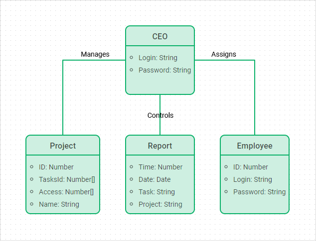
1.1.Class Diagrams
Class diagrams represent the static structure of a system. They showcase classes, their attributes, methods, and the relationships between them. This diagram is crucial for understanding the system's blueprint, as it defines the various objects, their data, and how they interact with one another. Class diagrams help in designing and implementing object-oriented systems by providing a clear map of the system’s architecture. Usage:
- To design and visualize the static structure of an object-oriented system.
- To document the system's classes, their attributes, methods, and relationships.
Advantages:
- Provides a clear blueprint of the system’s architecture.
- Helps in understanding the data and interactions among objects.
Disadvantages:
- Can become complex and hard to manage for large systems.
- Requires a good understanding of object-oriented principles to interpret correctly.
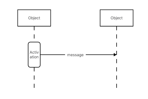
1.2.Sequence DiagramsSequence diagrams illustrate the dynamic interactions between objects over time. They show how objects communicate with each other through a sequence of messages. This is particularly useful for visualizing the flow of control in a system, understanding the order of operations, and ensuring that the system meets its functional requirements. Sequence diagrams are beneficial for designing and debugging complex interactions within the system. Usage:
- To illustrate the dynamic behavior of a system by showing how objects interact over time.
- Useful for visualizing the flow of control and message passing in a system.
Advantages:
- Helps in understanding the sequence of operations and interactions among objects.
- Useful for debugging complex interactions and ensuring functional requirements are met.
Disadvantages:
- Can become overly detailed, making them hard to read.
- Not suitable for depicting the overall structure of the system.
1.3.Use Case Diagrams
Use case diagrams depict the functional requirements of a system by highlighting the interactions between actors (users or other systems) and use cases (specific functions or processes). These diagrams are essential for capturing the user requirements and ensuring that the system delivers the expected functionality. They provide a high-level overview of the system’s functionality and the relationships between different use cases.
Usage:- To capture functional requirements and depict interactions between actors and the system.
- Useful for providing a high-level overview of the system's functionality.
Advantages:
- Simplifies the understanding of user requirements.
- Provides a clear view of the relationships between different use cases.
Disadvantages:
- May oversimplify complex interactions.
- Does not provide details on how the system will be implemented.
2.Entity-Relationship Diagrams (ERD)
ERDs are used to model data structures and relationships within a database. They play a crucial role in database design and development. ERDs depict entities (objects or concepts) and the relationships between them, providing a clear visualization of the data model. This helps in organizing data efficiently, ensuring data integrity, and facilitating database normalization. ERDs are fundamental in designing relational databases and understanding the data requirements of a system. Usage:
- To model and design the data structure of a database.
- Useful for visualizing entities and their relationships.
Advantages:
- Provides a clear visualization of the database schema.
- Helps in ensuring data integrity and efficient organization.
Disadvantages:
- Can become complex for large databases with many entities and relationships.
- Does not capture the dynamic behavior of the system.

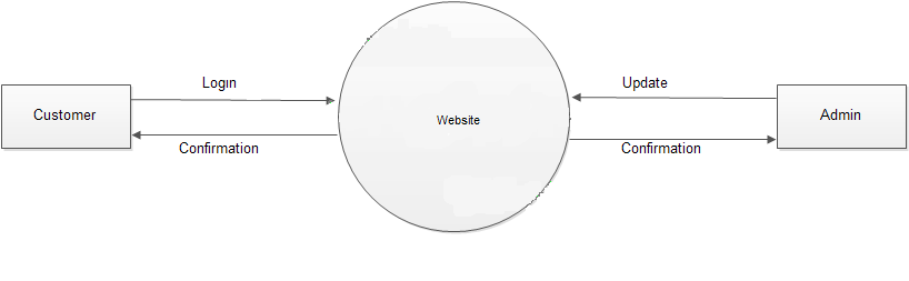
3.Data Flow Diagrams (DFD)
DFDs map out the flow of information within a system, illustrating how data moves from input to processing and output stages. They are used to represent the functional view of a system, showing how data is processed at different stages and how it flows between different components. DFDs help in understanding the data processing logic, identifying potential bottlenecks, and designing efficient data processing workflows. They are particularly useful in systems where data flow and processing are critical aspects. Usage:
- To map out the flow of information within a system.
- Useful for representing the data processing stages and flow between components.
Advantages:
- Helps in understanding the data processing logic and workflows.
- Useful for identifying potential bottlenecks and optimizing processes.
Disadvantages:
- Can become complicated for systems with extensive data flows.
- Does not provide detailed information about data storage or processing logic.
4.State Diagrams
State diagrams depict the states of a system and the transitions between them, useful for modeling systems with dynamic behavior. They show how a system transitions from one state to another based on events or conditions. State diagrams are essential for modeling reactive systems where the state changes in response to external inputs. They help in understanding the system’s behavior, ensuring correct state transitions, and designing state-dependent logic. Usage:
- To model the states of a system and transitions between them.
- Useful for systems with dynamic behavior and state-dependent logic.
Advantages:
- Helps in understanding the system’s behavior and state transitions.
- Useful for designing and validating reactive systems.
Disadvantages:
- Can become complex for systems with many states and transitions.
- May require additional diagrams to fully capture the system’s behavior.
5.Flowcharts
Flowcharts provide a step-by-step representation of processes, aiding in the visualization of algorithms and workflows. They use standardized symbols to represent different types of actions, decisions, and processes, providing a clear and intuitive way to understand complex procedures. Flowcharts are widely used in designing and documenting algorithms, troubleshooting processes, and optimizing workflows. They help in breaking down complex processes into manageable steps, making them easier to analyze and improve.
Usage:- To provide a step-by-step representation of processes, algorithms, or workflows.
- Useful for documenting and troubleshooting processes.
Advantages:
- Simplifies the understanding of complex processes.
- Provides an intuitive and easy-to-follow visualization.
Disadvantages:
- Can become large and unwieldy for complex processes.
- May oversimplify the logic of more complex systems.
Real-World Applications of System Modeling
System modeling is integral to various domains, contributing
to the development of robust and efficient software solutions. Here are some
notable applications:
- Healthcare
Systems:
- In healthcare, system modeling aids in designing Electronic Health Records (EHR) systems, ensuring seamless data flow, interoperability, and compliance with regulations
- E-commerce
Platforms:
- E-commerce
systems leverage modeling to streamline user interactions, manage
inventories, and optimize transaction processes.
- Financial
Services:
- Financial
institutions utilize system modeling to design secure and efficient
transaction processing systems, risk management solutions, and customer
relationship management (CRM) systems.
- Embedded
Systems:
- In
the development of embedded systems, such as those in automotive and
aerospace industries, modeling ensures the integration of hardware and
software components, enhancing reliability and performance.
Conclusion
System modeling in software engineering is more than just a
technical exercise; it is a strategic practice that drives the successful
development of complex software systems. By providing clarity, improving
communication, and ensuring quality, system modeling lays the foundation for
building software that meets user needs and stands the test of time.
As technology continues to evolve, the importance of system
modeling will only grow, empowering software engineers to tackle increasingly
sophisticated challenges. Whether you're a seasoned developer or a budding
software engineer, mastering system modeling is a journey worth embarking on,
promising a deeper understanding and greater control over the software
development process.
Comments
Post a Comment